
4. What is Phantom Source Shift?
- Issac Thomas

- May 13, 2022
- 7 min read
Updated: Jun 23, 2022
Recap and Introduction
In the previous two blogs I have explored the theory behind ORTF Recording and Binaural Audio, however, the focus of this research project is to further understand the similarities between the two. As a quick recap, this project is aiming to explore whether the ORTF microphone configuration can be used to provide a personalised binaural experience in interactive media (games, VR, etc.), without using traditional binaural synthesis methods (HRTF's).
Therefore, to gain a further understanding of the relationship between the two techniques, I have spent the last week going through the literature surrounding this area. In this blog I hope to share some of my findings, and dive into some of the theory and principles surrounding this topic.
A further look into the ‘Recording Angle’
In the previous blogs on ORTF Recording and Binaural Audio, I discussed how humans use Interaural Time-Difference and Interaural Level-Difference to determine where a sound is coming from. As a result, the benefit of using a stereo microphone configuration such as ORTF, is that the positional information of the sound source is preserved in the recording – but only to a certain extent, as will be discussed in this blog.
In the ORTF blog I also discussed the concept of the Recording Angle, which is the area in front of the microphone configuration that is captured by the microphones – this is represented in the diagram below.

Although near-coincidence stereo microphone techniques can capture the position of a sound source - thanks to their ability to capture Interaural Time and Level Differences– when you listen back to the recording, the perceived position of the sound will probably not match the position that the sound was recorded at. This is because sound source direction is susceptible to a concept known as ‘Phantom Source Shift’ (Wittek and Theile, 2002; Braasch, 2005).
What is Phantom Source Shift?
When you listen to a stereo microphone recording (ORTF in this case), through a stereo (2-speaker) playback system, the sound source that has been recorded will create what is known as a ‘Phantom Image’. A ‘Phantom Image’ just means that the sound source appears to be coming from a particular point in space.
Usually, we assume that the stereo playback system is created by placing 2 loudspeakers at ±30° from the listener to create an equilateral triangle, as shown below.

‘Phantom Source Shift’ is the perceived position of the Phantom Image when you listen back to the recorded sound source. Unlike the source angle (the angle of the sound being recorded in relation to the microphones) the Phantom Source Shift is written as a percentage (%) instead of in degrees (°).
Why is the Phantom Source Shift not the same as the Recorded Source Angle?
The Phantom Source Shift is not the same as the Recorded Source Angle because the Phantom Source Shift is affected by two main factors (Wittek and Theile, 2002):
The Recording Angle (as discussed above and in the in the ORTF Recording blog)
The position of the two playback speakers (e.g. Ideal speaker configuration, or headphones)
Effectively, the maximum points of the Recording Angle (which in ORTF is ±50°, since the total recording angle is 100°) are stretched or compressed to match the left and right extremities of a playback system. The images below represent the Phantom Source Shift of 4 spaced violins recorded with ORTF, played back through the Ideal Speaker Configuration and through Headphones.


As you can see in the diagrams above, the Phantom Images of the violins are compressed in the ideal speaker configuration. This is because the width of the playback system is less than the ORTF recording angle. However, when you listen to an ORTF recording through headphones, the Phantom Images are stretched because binaural hearing is wider than the recording angle.
Examples
Here is a performance of an acoustic guitar recorded using ORTF. Can you hear different sounds as Phantom Images? Perhaps focus on the sound of the right hand moving up and down the strings, and then focus on the main 'body' sound of the guitar.
Do the Phantom Images appear differently when listening through headphones or through speakers?
Here is another guitar recording with the microphone configuration further from the performer. Do you notice a difference in the Phantom Images?
Here is my favourite example! A full ensemble was recorded using only a single ORTF configuration. Can you hear each instrument as its own Phantom Image?
Why is the Phantom Source Shift given as a percentage (%)?
As discussed, the value for Phantom Source Shift is provided as a percentage (%), where the Left Speaker is equal to -100% and the Right speakers is equal to 100%. Therefore, if the sound is heard only from the left speaker, then Phantom Source Shift would be -100%. If the sound source was heard between both speakers, then the Phantom Source Shift would be 0%.
Even though the apparent location of the Phantom Images may change depending on the speaker configuration, the position of the Phantom Image be the same proportionally between the two speakers – this is why the Phantom Source Shift is given as a percentage and not as an angle.
Calculating the Phantom Source Shift
You can calculate the Phantom Source Shift using the ITD and ILD of a sound source (ITD and ILD is discussed in depth in the ORTF Recording and Binaural Audio blogs).
Wittek and Theile (2002) say that a 0.1ms increase in ITD will increase the Phantom Source Shift by about 13%.
They also say that every 1dB increase in ILD will increase the Phantom Source Shift by about 7.5%.
Both the ITD and ILD cues can be added together to get the total Phantom Source Shift. As discussed in the ORTF Recording blog, the ITD for ORTF ranges between 0-0.5ms, and the ILD ranges between 0-20dB.
How can we calculate ITD and ILD for each source direction?
As we know from the previous blogs, the ITD and ILD will change depending on the direction of the source. In the ORTF Recording blog I presented some equations that you can use to calculate the ITD and ILD for any source direction. I haven't included these in this post, however, they were used to calculate the ITD and ILD values below.
Example Phantom Source Shift Calculation
For a sound source positioned at 25° of an ORTF Configuration:
ITD ≈ 0.2ms --> 26% Phantom Source Shift
ILD ≈ 4dB --> 30% Phantom Source Shift
26% + 30% = 56% total Phantom Source Shift
If the Speaker configuration and Phantom Source Shift is known, then you can calculate the direction of the Phantom Image as shown below.
For an Ideal Speaker Configuration (±30°), the perceived Phantom Image Angle would be:
30 X 0.56 ≈ 17°
For Headphone Playback (±90°), the perceived Phantom Image Angle would be:
90 X 0.56 ≈ 50°
Imaging Assistant
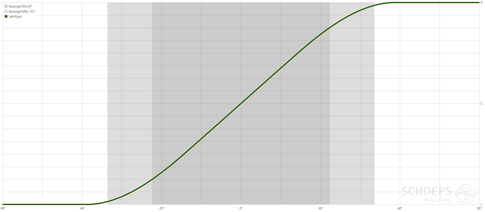
Calculating the Phantom Source Shift can be a painstaking task, but thankfully Hulmet Wittek (who works for Schoeps Microphones), has developed an app that calculates the Phantom Source Shift for any stereo or 3-channel microphone configuration. This is called the ‘Image Assistant’, and is available here (Wittek and Theile, 2002; SCHOEPS GMBH, 2022) .
The image below shows the Phantom Source Shift curve, also known as the ‘localisation curve’ for an ORTF configuration, taken from the ‘Image Assistant’ web app (SCHOEPS GMBH, 2022).
Reflective Summary - Driscoll's What Model (Driscoll, 2007)
What?
This week I have explored how phantom images are created using stereo microphone techniques. I have also continued to explore the relationship between ORTF recording and Binaural Audio. Phantom Images captured by an ORTF Recording are stretched or compressed to match the output format.
So What?
This aim of this blog was to further explore the similarities between ORTF recording and Binaural Audio. In doing so I have discovered that Phantom Images created from ORTF Recordings are typically compressed when heard though an ideal stereo speaker configuration, but stretched for when heard through headphones.
This did have me slightly confused, however, since we know that the ILD and ITD cues of ORTF are less than those of Binaural Audio? Surely, a source arriving at 25° can't appear as 50° in headphone listening? If I substitute the ±90° for headphone listening with ±45° I get the result of 25.2° which is almost perfect. Perhaps this is what I am doing wrong?
Unfortunately, most of the literature surrounding this area is focused on the 'ideal speaker configuration', but this project is more interested in headphone listening. To get a better understanding of this I need to further explore whether the theory of Phantom Source Shift applies to headphone listening in the same way as the ideal speaker configuration.
What Next?
In the upcoming blog I will be further exploring Object-Based Audio. However, over the next few weeks I will continue to research the area of Phantom Source Shift, and see if the same calculations actually apply to headphone listening in the same way.
Next, I will be also looking at how this concept applies to elevation (sounds coming from above or below). Unfortunately, the literature surrounding stereo microphone configurations focuses on the horizontal plane. Perhaps the best way to explore this topic would be to measure ITD and ILD at all points using an ORTFTF, as I suggested in the previous blog on Binaural Audio.
Conclusion
This blog has looked at how sounds recorded using a stereo microphone recording appear as a Phantom Image when they are played back through a stereo playback system. The Phantom Image will appear as though it is coming from a position in space, however, this will probably not be the same as the original source direction due to a concept known as ‘Phantom Source Shift’.
Phantom Source Shift can be calculated from the ITD and ILD of a source, however, the ‘Image Assistant’ app provides a much faster way of accessing this information.
Having a good understanding of Phantom Source Shift is important for this project, as this project is looking to explore the similarity between ORTF recording and Binaural Audio. So far, I have discovered that sound sources recorded within the ‘Recording Angle’ will be stretched or compressed to match the width of the playback system.
References
Braasch, J. (2005) ‘A Binaural Model to Predict Position and Extension of Spatial Images Created with Standard Sound Recording Techniques’, in. Audio Engineering Society Convention 119, Audio Engineering Society. Available at: https://www.aes.org/e-lib/browse.cfm?elib=13352 (Accessed: 4 May 2022).
Driscoll, J. (ed.) (2007) Practicing Clinical Supervision: A Reflective Approach for Healthcare Professionals. Edinburgh: Elsevier.
SCHOEPS GMBH (2022) Image Assistant | SCHOEPS Microphones, Schoeps Mikrofone. Available at: https://schoeps.de/en/knowledge/image-assistant.html (Accessed: 7 May 2022).
Wittek, H. and Theile, G. (2002) ‘The Recording Angle - Based on Localisation Curves’, in. Audio Engineering Society Convention 112, Audio Engineering Society. Available at: https://www.aes.org/e-lib/browse.cfm?elib=11307 (Accessed: 4 May 2022).


Comments